 Add hardness tester to Favorites!
 Add hardness tester to Favorites!
Home About us Industrial products Contact us Distributors
 |
Leeb hardness tester ( new) HT6561Product synopsis |
|||||||||||||||||||||||||||||||||||||||||||||||||||||||||||||||||||||||||||||||||||||||||||||||||||||||||||||||||||||||||||||||||||||||||||||||||||||
|
CONTENTS ..................................... 1 Features and Specifications .11.1 Typical Applications..................................................1 1.2 Testing Features.......................................................1 1.3 Technical Specifications............................................1 1.4 Measuring and Converting Ranges.............................2 1.5 Configuration...........................................................2 2 Structure Feature &Testing Principle .........................22.1 Structure Feature......................................................2 2.2 Leeb Hardness Testing Principle................................4 2.3 Symbols and illustrations of hardness scale................4 2.4 Symbols of materials…………………………...........……5 3 Preparation ...............................................................53.1 Weight Requirements ...............................................5 3.2 Roughness Requirements................................. . . . . ...6 3.3 Cleanliness Requirements........................................6 3.4 Stability Requirements..............................................6 3.5 Samples with curved surfaces ...................................7 3.6 Test Samples Properties...........................................7 4 Operation of the Tester ..............................................74.1 Power On/Off...........................................................7 4.2 Setting your Impact Direction................................ . . ..7 4.3 Selecting a material..................................................8 4.4 Choosing a hardness scale........................................8 4.5 Average Times Setting..............................................8 4.6 Measuring Procedure...............................................8 4.7 Data Memorizing......................................................10 4.8 Memory Recall.........................................................10 4.9 Delete Data in Memory..............................................10 4.10 Download to PC.....................................................10 4.11 Auto Power Off............................................... . . ......10 4.12 Battery Replacement..............................................10 5 Calibration ................................................................106 Maintenance & Servicing ...........................................11page: 1 Quick Start Guide To quickly configure the tester and start taking readings. Please follow the procedures below. 1. Preparation for work pieces to be tested Thick, heavy, and solid workpieces are preferred for testing whenever possible. the surface must be polished and limited to Ra ≤ 2μm. The light workpiece to betested should be fixed to a bearing or support to avoid bending, deformation, and displacement during testing. 2. Operation of the tester 2.1 Fit batteries Install batteries paying careful attention to polarity. 2.2 Power on Press the POWER/MENU key to power the tester on.2.3 Set Impact Direction by press DIR/SHIFT key2.4 Select a material code See Part 4.3 2.5 Select a hardness scale See part 4.4 2.6 Place the tester onto the surface to be measured 2.7 Load 2.8 Release Notes: 1. Never try to let tester strike any tungsten steel or harder materials. Otherwise the impact body will be damaged forever. 2. Under no circumstances should you press the release button if the tester was not against the work piece. Otherwise the support ring would be loose easily. page 2 1 Features and Specifications 1.1 Typical Applications * Die cavity of molds * Inspection of bearing and other mass produced parts on a production line * Failure analysis of pressure vessel, steam generator and other equipment * Inspection of installed machinery, permanent parts of assembled systems and heavy work pieces. * Testing surface of a small hollow space * Material identification in the warehouse of metallic materials * Rapid testing in large range and multi-measuring areas for large-scale work piece 1.2 Testing Features * Palm size for narrow space. * Test at any angle, even upside down. * Direct display of hardness scales HRB, HRC, HV, HB, HS, HL. * Large memory could store 250 groups including single measured value, impact direction, material and hardness scale etc. * User recalibration function allowed. * Can communicate with PC computer for statistics and printing by the optional cable. * Manual or automatic shut down. * Low battery indication. 1.3 Technical Specifications Display: 12.5mm LCD with back light Accuracy: Display error ±0.8% at LD=900 Measuring range: 200-900L Conversion: HL-HRC-HRB-HB-HV-HSD Materials: 9 different common materials With RS232C interface Memory: 250 data can be stored and re-readable Impact device: D Will handle the majority of hardness testing applications. Weight: 75g Power supply: 2x1.5V AAA size battery Dimension: 146×65×36mm Weight: 130g (not including batteries) Working temperature : - 10℃~+50℃Storage temperature :- 30℃~+60℃;Relative humidity: ≤90%1 1.4 Measuing and converting Ranges table 1.1
1.5 Configuration
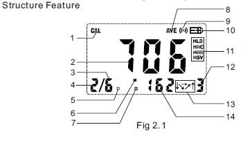
2 Structure Feature testing principle 2.1 structure Feature:
1 Calibration mode 2 Measuring value 3 Average times set 4 n th measuring value5 Impact type 6 Measuring state 7 Browsing state 8 Average Symbol 9 Measuring symbol 10 Battery indicator 11 Hardness scale 12 Material 13 Direction 14 Number of memorized data
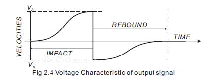
3 2.2 Leeb Hardness Testing Principle An impact body with a spherical test tip made of tungsten carbide is propelled against the sample surface by a spring force and then rebounds back. At a distance of 1mm from the sample surface, the impact and rebound velocity of the impact body are measured by the following method: A permanent magnet embedded in the impact body, when passing through the coil in its coil holder, induces in the coil an electric voltage proportional to the velocities of the magnet. Leeb hardness is expressed by the following formula: HL=1000×(VB /VA ) Where: HL is Leeb Hardness VB is the rebound velocity of the impact body BVA is the impact velocity of the impact body AThe voltage characteristic of output signal, when the impact body passes through the induction coil is illustrated in the following figure:
A Leeb’s Hardness Tester measures the hardness of sample material in terms of Hardness Leeb (HL), which can be converted into other Hardness units (Rockwell B and C, Vicker, Brinell and Shore D). When measuring the hardness of a sample material using the traditional static hardness testing method, a change of applied pressure will result in a change in the hardness reading. This will also happen during a Leeb’s Hardness test when you change the impact device. In measuring the hardness of the same test sample with different impact devices, the Leeb’s hardness values obtained will vary. For Example: 760 HLD ≠760HLC≠760HLG2.3 Symbols and illustrations of hardness scale
2.4 Symbols of materials
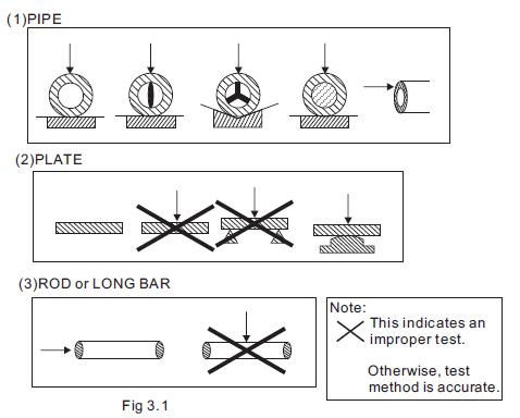
3 Preparation Selection of the workpiece to be tested and preparation of its surface prior to testing will help insure accuracy. Magnetism of the sample itself should be avoided. The surface temperature of sample should be less than 120 °C. 3.1 Weight Requirement To achieve correct test results, select thick, heavy, and solid workpieces for testing whenever possible. The surface area where the impact body strikes should have an even hardness. A solid workpiece that weighs more than 11lbs. (5Kg) can be tested on directly with the this hardness testers. Support is not necessary for heavy sample. A workpiece that weighs 6 to 11lbs. (3 to 5Kg) should be fixed to a bearing or support weighing over 11lbs (5kg) to avoid bending, deformation, and displacement during testing. A workpiece that weighs less than 4 lbs. (2Kg) should be secured to a workbench or a stable support. The surface between the workpiece and the support must be hard, clean, and smooth. To secure the workpiece, apply petroleum jelly or yellow grease to the adjoining surfaces of the workpiece and support, press the workpiece firmly onto the support, and eliminate any air between the two surfaces by moving the workpiece back and forth. Proper coupling requires a little experience. Insufficiently coupled samples produce large variations of individual measurements, HLvalues which are too low and the operation is characterized by a rattling noise upon impact of the test tip. For the coupling operation, the following prerequisites must be fulfilled: * The contact surface of the sample and the surface of the base plate must be flat, plane parallel and ground. * The direction of the test impact must be perpendicular to the coupled 5 surface. * Minimum thickness of the sample for coupling (3mm). 3.2 Roughness Requirement To eliminate measurement errors which could result from the roughness of the test surface, the surface should be polished so that a metallic luster appears. The roughness (Ra) of the surface must be limited to ≤2μm. Note that the rougher the surface of the workpiece, the lower the hardness test results. 3.3 Cleanliness Requirements To ensure test accuracy, the test surface of the workpiece must be clean and free of any oil stains, rust, and remains from electro-plating or paint. 3.4 Stability Requirements To avoid displacement during testing, the workpiece should be firmly fixed with its test surface perpendicular to the impact direction. Due to the impact of the Impact Body, the test area may deform or vibrate, even for some workpieces with suitable weight and thickness. The tested hardness may be lower than normal. This is especially true for workpieces such as a large plate, a long bar or a rod, and workpieces with a curved surface. Some testing recommendations for these workpieces are shown in figure 3.1
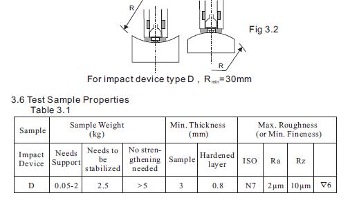
6 3.5 Samples with Curved Surfaces The larger the curvature of the workpiece’s surface, the easier the testing operation. Under normal conditions, testing can be done directly with the standard support ring to a curvature with radius of 1 3/16” (30mm) or longer. For a workpiece with a radius of less than 1 3/16” (30mm), a special support ring should be used for testing.
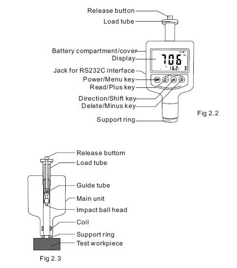
4 Operation of the tester 4.1 Power on/off * Press the POWER/MENU key, now power is on. The instrument is inworking mode. * The LCD will display the same settings that were previously set. If the display meets your current testing requirements, you can start the test immediately. If not, you can enter your required settings using the keypad. * The tester can be turned off by pressing the POWER/MENU key for 3seconds while OFF shows on the display. 4.2 Setting your Impact Direction Use the DIR/SHIFT button to move the cursor until you reach the desireddirection. 4.3 Selecting a material Press the DIR/SHIFT key first and not release it. Then presskey to scroll down the list until the desired material is reached. 4.4 Choosing a hardness scale Press the DIR/SHIFT key first and not release it. Then press keyto scroll down the list until the desired hardness scale is reached. 4.5 Average Times Setting After pressing POWER/MENU key for 6 seconds into item AVE,press key or key in turn to select the average times from 2-9, selecting 0 means no mean values. Press POWER/MENU keyfinally to exit from the operation This function allows you to view the average of the amount of tests you entered. Example: If you chose “3”. The tester will show the average after 3 consecutive tests. 4.6 Measuring Procedure Use standard test block to check your hardness tester prior to a hardness test. 4.6.1 Loading Push the Loading Tube towards the support ring to lock the impact body. Then, while still holding on to the loading tube, slowly return it to its original position. Caution: Returning the Loading Tube back to its original position tooquickly may damage the tester’s parts. ALWAYS hold onto the Loading Tube and slowly guide it back in a controlled fashion.
4.6.2 Placement Holding the tester between your thumb and index finger, hold the tester against the Work piece. Please note: the impact device must be firmly against the surface and the impact direction should be vertical to the testing surface or you may get unsatisfied value. 4.6.3 Releasing Press the release button lightly on top of the tester and take measurement. The measuring value will be displayed on LCD. To be sure that while releasing the triggering button, the work piece, the impact device and the impact body are all stable and the starting force coincides with the axis of the impact device. POWER MENU RD DIR SHIFT DEL MATE SCALE If the test results are outside the ranges listed in Table 1.1, the screen will display E. Note: Under no circumstances should you press the release buttonif the tester was not against the work piece. Otherwise the support ring would be loose easily. Each measure area of the sample usually needs 3 to 5 times of testing operation. The result data dispersion should not more than mean value±15HL. The distance between any two impact points or from the center of any impact point to the edge of testing sample should conform to the regulation of Table 4.1 If want accurate conversion from the Leeb hardness value to other hardness value, Just operate as per procedures listed in part 4.4
| ||||||||||||||||||||||||||||||||||||||||||||||||||||||||||||||||||||||||||||||||||||||||||||||||||||||||||||||||||||||||||||||||||||||||||||||||||||||