 Add to Favorites!
Home About us Industrial products Contact us Distributors Chinese site
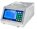
Air particle counter LZJ-01D AC/DC
ˇˇ Overall Size:290ˇÁ220ˇÁ140 Weight :3.5kg Power: AC/DC powered Enclosure: stainless steel Sampling Łş2.83L/min
Particle Counter OperatorˇŻs Manual ˇˇ Type: LZJ-01D Content I Diagram of front and rear panelsˇˇˇˇˇˇˇˇˇˇ.ˇ. 1 II Outlineˇˇˇˇˇˇˇˇˇˇ.ˇ. ˇˇˇˇˇˇˇˇˇ...2 III Technical parametersˇˇˇˇ.ˇ. ˇˇˇˇˇˇˇˇˇ....3 IV Use conditionsˇˇˇ.....ˇˇˇˇ.ˇ. ˇˇˇˇˇˇˇˇ3 V Methodˇˇˇˇ.ˇ. ˇˇˇˇˇˇˇˇˇ..........................3 VI Attentionˇˇˇˇ.ˇ. ˇˇˇˇˇˇˇˇˇ.....................11
LZJ-01D particle counter (Laser large-screen LCD with both AC and DC)
I Size and weight Dimension: 220mm (Width) ˇÁ 285 mm (Depth) ˇÁ 140 mm(Height)
Weight: 3.8kg
II Outline LZJˇŞ01D particle counter is manufactured based on the light scattering theory of particles. Light will be scattered on particle surface when the light beam touches particles. The intensity of scattering light is related to the intensity of light source and particle size. With the same light source, particle size could be obtained by measuring the intensity of scattered light. When the location of the light source is fixed and particles go through the light beam by the air pump, light will be scattered during the process. The intensity of light scattered is dependent on the particle size. Light will be scattered n times when particle number is n, thus n light pulses are generated. They become n pluses after the photoelectric conversion. Measurement of particle size and number is made with the light scattered on particles. LZJˇŞ01D particle counter has a laser large-screen LCD and it is applicable for both AC and DC. It has unique features including: 1 Use of imported semiconductor laser tube and imported semiconductor photosensitive receiver; 2 The core component of the entire instrument, light scattering sensor, is the crystallization of the factory from many years of painstaking research. Its structure is unique in the country, which significantly eliminate the stray light of the cavity, and signal to noise ratio is greatly improved, so that the measurement is reliable. It has been patented in China. 3 The confidence level of the instrument was measured in accordance with the GB/T16292-1943896, which requires determining the cleanliness level automatically by two conditions. The method of cleanliness determination of this instrument is more comprehensive than other similar products in China which only use one condition. This instrument is more in line with national standard. 4 The instrument can store up to 1000 measurement data and query historical data in time. 5 The measurement data can be connected to computer for data communications (Optional). 6 Temperature and humidity can be measured simultaneously during the process of particle sampling when the temperature and humidity sensor transmitter are added with userˇŻs requirement (Optional). 7 The instrument is the unique one in China which shows the sampling air volume with digital displayer, and it is more intuitive and accurate. III Technical parameters According with JJF 1190-2008 ˇ°Calibration Specification for Airborne Particle Counterˇ± 1. Insulation resistance of whole machine (normal atmosphere) ˇÝ20M¦¸ 2. No arcing and breakdown phenomena will occur when the whole instrument is kept under pressure with AC1.5kV/50Hz for 1min 3. Self-cleaning time ˇÜ 10minˇŁ 4. Relative error of air flowrate < ˇŔ5%ˇŁ 5. Timing error: ˇŔ1 s during 6 min of timing process 6. Repeatability: under the same conditions, the repeatability of continuous particle concentration sampling is ˇÜ10% FS 7. Particle size distribution errorŁĽˇŔ30% for particle size channels 0.5¦Ěm and 5¦Ěm 8. Particle concentration display errorŁĽˇŔ30% FS for particle size channel 0.5¦Ěm when the instrument is under normal condition IV Use conditions 1. Maximum particle concentration ˇÜ 3ˇÁ104 pc/L 2. Normal atmospheric pressure 3. Power supply : AC, 220VˇŔ5%, 50Hz 4. No interference of strong magnetic field around V Method 1 Turn on (1) AC power: bring out the AC/DC transform line, insert the AC plug into the AC 220V power outlet, and insert the other end of the DC plug into the charging plug port on the rear panel of the instrument. Then press the power switch button on the left bottom of the rear panel. When the screen is displaying (first screen) as shown in Fig. 1, the boot process is complete. (2) DC power: when the battery is already installed inside the instrument, press the power switch button, and then the display shows the first screen. (3) Battery installation: when the battery is not installed, please remove the two fixed screw on the lid of the rear panel, and put the battery in. Make sure the battery has the same direction "+" "-" with that of indications inside the box. Cover the lid and then tighten the screws. (4) Turn on the power switch button on the rear panel, the display will show the schematic diagram below, which means the boot is performed properly.
Fig.1 Boot display Fig.2 Parameter setting screen
2 Parameter setting (1) Tools for modifying and setting parameters A ˇ°ˇřˇ± button is the number key to choose number from 0 to 9 or from 9 to 0; B ˇ°¨‹ˇ± button is the shift key, ˇ°ˇńˇ± is the indicator to move upwards or downwards, ˇ°¨€ˇ± is the indicator to move left or right; C ˇ°Enterˇ± button means to choose the selected or modified data. (2) Methods for modifying When a parameter needs modified, please press the ˇ°¨‹ˇ± button, and move the ˇ°ˇńˇ± indicator onto this parameter, and then press ˇ°Enterˇ± button. Below the first number of this parameter, the left/right indicator ˇ°¨€ˇ± will appear, which means this number is amendable. Please press the ˇ°ˇřˇ± button to change the number. When the ˇ°ˇřˇ± button is pressed, the left/right indicator ˇ°¨€ˇ± will move to the next number. When the parameter setting is finished, please press ˇ°Enterˇ± button. 3 Instruction of parameters on the screen (1) Date: 00yy00mm00dd according to Gregorian Calendar; (2) Time: 00h00mŁşBeijing Time; (3) Operating parameterŁşParameter channel for the second screen as shown in Fig. 2; (4) Confidence level UCL A:00ŁşSampling point number for monitoring the cleanness level; (5) Delete dataŁş0ŁşAfter changing 0 to 5, press ˇ°Enterˇ± button. When 0 is modified to be 9, it means all the data stored are deleted, so please be cautious; (5) Sample locationŁş000ŁşUser could set the location numbers for the sampling points; (6) CycleŁş00h00m00sŁşThe time interval for regular calibration; (7) Continuous measurement times: 00ŁşIt means the number of measurement times for cleanness level determination (usually 2-3 times every sampling point) or the needed sampling times N between the start of the sampling and the end (interval, delayed time) for normal (random) sampling; (8) Sampling interval: 000sŁşIt means the time needed when moving the instrument from one sampling position to another or the stop time constant after the N times normal (random) sampling is stopped. (9) Time delayed: 00s: In field test, the time delayed parameter can be set to postpone the sampling, so that the instrument can reach stable after a certain time before sampling; (10) Alarm level: 0 : When the required ISO cleanness level of the room is set (e.g. the number 6 representing 1000 level is set), the instrument will stop sampling temporarily and generate alarming sound once the detected data is greater than the specified cleanness level. After alarming for a certain time, the instrument will continue to sample automatically. When it is set 0, the alarming apparatus will be close. (11) Standard selection: ISO14644 (Code:1), 209E(Code:2), Pharmaceutical GMP static (Code:3), GMP dynamic (Code:4) 4 Field measurement: normal monitoring (randomly), certified monitoring (UCL) (1) normal monitoring (randomly) A. After warm-up for 3-10 minutes, parameters such as date, time, cycle, continuous sampling times can be set and choose the right numbers with the ˇ°Enterˇ± button. Fig. 3 Display the measurement information on screen B. Choose the sampling location and place the instrument in the right place. After the measurement tripod support is positioned, remove the sampling tube from the back and connect to the sampling probe. C. Press ˇ°Testˇ± button and the sampling starts after the time delayed is complete. Screen shows the information. After each test, the screen shows the measured result for each particle size. If the ˇ°Observeˇ± button is pressed, the change of particle number with the time can be seen. The environment is dirty when it changes rapidly, and vice versa. (2) certified monitoring (UCL) A. Turn on the power and press ˇ°resetˇ± button. Set the sampling point number, sampling times, sampling interval and time delayed; Please refer to JGJ71-90 (when the sampling points are more than 9, cleanness will be determined without UCL); B. Procedure: Click the ˇ°Confidence levelˇ± button. When the sampling process finished on the first point, the instrument will generate the beep sound. Then the instrument can be moved to the second sampling point and at the same time it will go into the countdown process of ˇ°sampling intervalˇ± automatically. When the instrument is located on the second sampling point and the countdown process is close to the end, the instrument will enter the countdown process within the ˇ°time delayedˇ±. After the countdown process is complete, sampling on the second point begins. After the completion of the second point sampling, the same procedure is applied on next points until the cleanness level is calculated and determined.
Fig.4 Confidence level screen C. Measurement result: when the last sampling process of the last point is complete, the screen will display the UCL according to the statistical method with 95% confidence level and the cleanness level will be determined based on the average maximum concentration of each sampling points as shown Fig.5. 5. Instructions for button use (front panel layout) (1) ˇ÷, ¨Ś: they are usually used to increase and decrease numbers. ˇ÷ key can be used to modify the parameter number from 0 to 9 or from 9 to 0. ¨Ś key is for shifting the position up and down or left and right. Fig. 5 Judgment screen (2) Enter : ˇ°Confirmˇ± the chosen parameter number; (3) Store : please click the button to store the measurement result during each test; (4) Print : Click the button to activate the printer, and click again to cancel this function; (5) Paper delivering : When this button is clicked, the printer paper walks out for a certain distance and then stop automatically; (6) Particle size Shield : When these two buttons are used together, the screen will not display some particle size channels. They will appear when these two buttons are clicked again; For example, if only two particle size channels 0.5µm and 5µm are needed shown on the screen and other particle channels do not need displayed, please follow the steps: click the ˇ°particle sizeˇ± button until the indicator ˇń is on the channel 0.3µm, and click the ˇ°shieldˇ± button to remove the display and recording function to this channel, and then press the ˇ°¨‹ˇ± button to move ˇń to 1µm where display and recording of the channel will stop after the ˇ°shieldˇ± button is pressed. With this procedure, particle size channels 3µm and 10µm can be removed, only to leave channels 0.5µm and 5µm on the screen. On the contrary, particle size channel where ˇń is located will appear again as long as the ˇ°shieldˇ± button is clicked again. (7) Confidence level : it is used for calculation of confidence level; (8) Sampling : It is used for normal monitoring and measurement result will appear after a cycle of sampling; (9) Observe : It is used to display the change of particle number during the measurement; (10) Temp.&Humidity : After the corresponding sensors are connected to the temperature and humidity port on the rear panel, both temperature and humidity will appear on the screen when this button is clicked; (11) Inquiry : It is used to query the stored data, and the screen displays a query screen. (12) Reset : This button is used to display the boot screen; (13) pc/m3 : This button is used to convert the particle concentration unit into pc/m3;
Fig. 6 Query screen
Query procedure: click the ˇ°queryˇ± button and the query screen appears. When the indicator is located on the date, please click ˇ°ˇřˇ± and ˇ°Enterˇ± button to modify the date. Click the ˇ°¨‹ˇ± button to move the indicator ˇ°ˇńˇ± to the time item. Then modify the time and click ˇ°Enterˇ± button to confirm. Click the ˇ°¨‹ˇ± button to move the indicator ˇ°ˇńˇ± to the query item. Click ˇ°Enterˇ± button to query. Once the instrument starts to query, the screen will show the stored data. Click ˇ°¨‹ˇ± and ˇ°ˇřˇ± buttons to move forward or backward to the corresponding stored data. 6. Use of printer (1) Instructions of the printer panel ˇń SEL self-test / online / offline switch; ˇń LF paper feeding switch; ˇń ˇřEject button; ˇń The green light shows the status of the printer which works online or offline;
(2) Replacing the paper roll ˇń Click the eject button ˇř on the bottom right corner of the printer, then the printer core will pop-up; ˇń Flip the machine core forward, and expose the paper reel ˇń Pinch the paper reel, pull the two short axis of plywood gently, and remove the paper shaft. ˇń Put the new paper roll onto the paper shaft and back in place. ˇń Cut the paper roll to the arrow shape. Click the ˇ°Paper deliveringˇ± button when the paper is inserted into the paper feed mouth on the bottom of the instrument until part of the paper is exposed. Click the ˇ°Paper deliveringˇ± button again to stop paper feeding. ˇń Reset the printer for future use with the above procedures; (3) Replace the ribbon The ribbon cartridge in the printer is already installed. When replacement is needed, please follow the following steps: ˇń Click the ejector button ˇř on the bottom right corner of the printer, and the machine core of the printer will pop up; ˇń Pull the clip on the bottom of the printer panel gently, and move the panel forward until the printer head is exposed. ˇń Lift the right side of the ribbon cassette, lift the left side, and then remove the ribbon cassette. ˇń Put the right side of the new ribbon cassette onto the gear shaft gently. If it is not allowed to fall in the end, rotate the knob on the ribbon cassette clockwise gently, until the right side of the ribbon cassette all in the end. Put down the left side of the ribbon cartridge. Check if the ribbon cassette is straightened. When it is exposed outside the ribbon cassette, please rotate the knob to correct the direction. ˇń Reset the printer panel, and insert the machine core into the printer box. 7. Shutdown (1) After the complete of measurement, disconnect the sampling tube from the sampling prove and then connect it to the self-cleaning mouth on the rear panel. The self-cleaning process last 2-3 minutes and the count number is close to 0. (2) Put away the sampling probe and the tripod support. Turn off the electricity switch of the instrument. (3) Unplug the power line and put it in order in the delivery box together with the instrument. 8. Instruction of the data acquisition software Firstly, install the software on the PC with the disc. After complete, double click the icon of the analysis software of the particle counter. Choose ˇ°Small flowrateˇ± on the item of ˇ°product type selectionˇ±; choose ˇ°V4Xˇ± on the item of ˇ°product version selectionˇ±. Then the data acquisition interface will appear after the ˇ°Enterˇ± button is pressed. Secondly, set COMM parameters. Click COMM setting icon on the interface and a setting dialogue will appear. Please set the COMM port at first and make sure this port is corresponding to the communication port of the PC. The Baud rate is set to 9600. The checksum is set to ˇ°Nonˇ± and click ˇ°Enterˇ± to make setting successfully. Thirdly, connect the instrument to the computer communication port with the communication line. Be sure the computer port is set consistently with the COMM port. Fourthly, perform data collection. Click on the data acquisition icon and the instrument will collect the data automatically. At last, click the query icon on the interface and choose the data as needed. Click on the ˇ°Exportˇ± icon on the interface and all the data will be saved to the EXCEL format. VI Attention
(1) The instrument is only used in the cleanroom; (2) The maximum length of the sampling tube is 3m; (3) Operators cannot exceed 2 and should stay away from the instrument; (4) The instrument electrical outlet must be three phase socket. The copper of the jack must be grounded to ensure safety.
Reference Cleanness level classification specified in ISO14644 and traditional classification
Cleanness Level of airborne particles in Cleanroom and Clean Area China National Standard GB50073-2001
ˇˇ ˇˇ | |||||||||||||||||||||||||||||||||||||||||||||||||||||||||||||||||||||||||||||||||||||||||||||||||||||||||||||||||||||||||||||||||||||||||||||||||||||||||||||||||||
Rinch Industrial Co.,Limited
Address: Room302, Building 17 No.35 Dedu road, Baoshan, Shanghai China Zip code: 200941
Tel: 86-21-36300944 Fax:86-21-36300944 Msn:goodluckvon@hotmail.com
cnrinch@yahoo.com.cn